
2026-08-03
UUGreenPower
0
Grid electricity does not travel straight from the utility connection to an EV battery. It first passes through input protection and switching equipment, then through power conversion, DC distribution, the charging cable and the vehicle inlet. The EV charging module sits at the conversion stage. Its job is to turn the available electrical input into controlled DC output, but it is only one part of the complete charger.
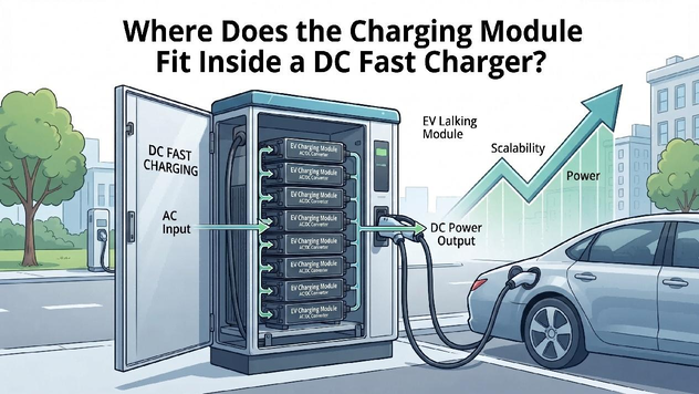
Charging Module Position in the Charger Architecture
In an all-in-one charger, the conversion units, controller, distribution hardware, display and connector system are normally housed in the same enclosure. In a split charger, several units may be grouped in a separate power cabinet that feeds one or more dispensers. Multiple units are commonly connected in parallel so the charger can build a higher total output and allocate power among connectors. Their exact position therefore depends on the cabinet architecture rather than on one universal physical layout.
Controlled Power Conversion During a Charging Session
After a vehicle is connected, the charger controller completes safety checks and communicates with the vehicle. It then sends a voltage and current command to the power-conversion stage. Each active unit regulates its share of the requested output, measures operating conditions and reports status. As the vehicle battery warms, cools or reaches a higher state of charge, the requested current can change. The module follows those controlled commands; it does not independently decide how fast the vehicle should charge.
System Boundaries, Protection, and Component Roles
The EV charging module works with AC input equipment, busbars, contactors, DC distribution, insulation monitoring, a charger controller, metering, a display, cable management and connectors. Vehicle communication, user authorization, payment, OCPP connectivity and site load management are normally handled outside the individual conversion unit. This distinction matters because a well-specified module cannot compensate for undersized conductors, poor airflow, weak protection coordination or unstable system software.
Module-Level Protection and Fault Response
What the unit protects—and what it does not. Typical module-level functions can include overvoltage, overcurrent, short-circuit and overtemperature response, as well as fault reporting. Complete-charger safety also depends on emergency-stop circuits, protective devices, enclosure design, insulation supervision, connector temperature monitoring and correct grounding. A module alarm must therefore be mapped to a defined system response. Engineers should know whether one fault causes graceful power reduction, isolates only one unit or stops the entire connector.
Component Roles in the UUinside Architecture
A useful component-relationship example. The UUinside platform describes PMU, ACU, DCU, DSU and CMS roles within a coordinated charger design. In simple terms, the PMU performs power conversion, the ACU manages the AC input, the DCU routes DC output, the DSU supports the user-facing dispenser and the CMS manages the cable. The example helps clarify why the conversion unit is central without being the whole charger. Actual component combinations still depend on connector current, cabinet power and project requirements.
Can Wallbox EV Charging Support Renewable Energy Integration?
2026-07-21 NextAt What Power Level Is EV charging Considered DC Fast Charging—and How Are Modules Configured?
2026-08-03

