
2026-09-02
UUGreenPower
0
A 1000V label answers only the upper output limit of an EV charging module. It does not prove the current and power available at the 400V and 800V points a charger must serve. The buyer’s decision is therefore whether the named model has usable evidence at those operating points—not whether the label sounds high enough.
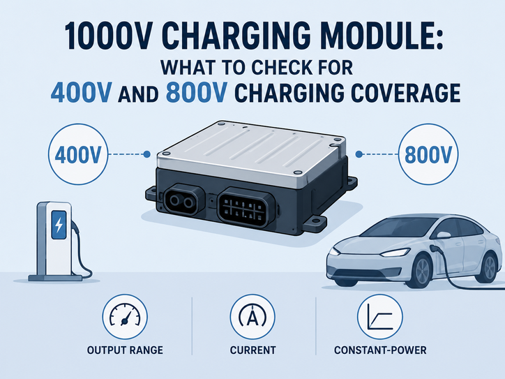
Write the 400V/800V operating-point check
Record the vehicle or battery voltage window, required power and current, concurrency assumptions, thermal condition and complete-charger interfaces. Keep this charger-level requirement separate from the module fields. A point below a stated constant-power range may still merit investigation, but the catalogue alone does not authorize a full-power conclusion.
Separate the two catalogue fields
The named UUGreenPower entries show why a 1000V label must be read with its constant-power range.
Named model | Output range | Constant-power range | Current | Temperature / derating |
UR100040-IP65(EU) | 150–1000VDC | 300–1000VDC | 0.5–133.3A | −40°C to 75°C; from 55°C |
UR100040-SW(EU) | 150–1000V | 300–1000V | 0.5–133.3A | −40°C to 75°C; from 55°C |
UR100040-LQ(EU) | 150–1000V | 300–1000V | 0.5–133.3A | −40°C to 75°C; from 60°C |
UR150027L(EU) | 200–1500V | 300–1000V | 0.5–106.6A | −40°C to 75°C; from 60°C |
The first three entries have an output range beginning at 150V while the documented constant-power range begins at 300V. UR150027L(EU) reaches 1500V in its output field, but its constant-power range remains 300–1000V. It must not be rewritten as 300–1500V constant power. These are model-level catalogue fields, not vehicle-compatibility or complete-charger evidence.
Run the 400V and 800V check
For each named model:
1. Mark the project’s actual 400V and 800V operating windows.
2. Place those points against the stated output and constant-power fields.
3. Record the current required at each point, not only the headline maximum.
4. Mark whether the point is inside a quoted range or requires controlled supplier data.
5. Keep cable, connector, cabinet and vehicle-control limits in the complete-charger review.
If the project requires full power below the documented constant-power range, ask for a model-specific test condition or revise the requirement. Above 1000V, the UR150027L(EU) output field can support an operating-envelope question, but it does not establish constant power at the higher voltage.
Keep thermal and cooling wording bounded
The named IP65 and SW entries list −40°C to 75°C and derating from 55°C; the liquid-cooled entries list the same operating range and derating from 60°C. These start points are not a complete derating curve, and they do not prove vehicle compatibility, connector performance or system thermal behavior. For SW models, retain the catalogue wording Cooling: Air or “Cooling Air”; do not upgrade it to “Direct Air Cooling.”
Use a three-stage evidence request
Stage 1 — catalogue boundary. Confirm the exact model, output range, constant-power range, current, operating temperature, derating start and cooling wording.
Stage 2 — application points. Send the project’s 400V, 800V and other mandatory points to the supplier. Ask for current and power at those points, with temperature, airflow or liquid-loop conditions and the model/version.
Stage 3 — system validation. Check cable, connector, cabinet, controller and vehicle-side assumptions in the complete charger. A module response can close a module row; it cannot close the system row.
Save the response with its document revision and unresolved-value log. If the request falls outside a stated range, ask what controlled evidence is available rather than asking the supplier to repeat the headline.
Make the operating-point decision auditable
The check should leave one row for each mandatory voltage point. Record the model and revision, requested power, required current, stated output range, constant-power status, test condition and the person who accepts the interpretation. A point can be supported when the catalogue or controlled test explicitly covers it, conditional when a named application test is still open, or held when the missing value could change the charger architecture.
Do not turn an output maximum into a pass by rounding the vehicle voltage. If the project operates near the edge of a range, retain the unit, tolerance and condition exactly as supplied. If the current requirement is below the maximum but the power point is outside the constant-power range, the row remains a question for the supplier. The same record should identify the cable, connector and controller assumptions that the complete charger must close.
This is why the 1000V label can be useful without being decisive. It narrows the model-level question, while the 400V/800V check connects the label to the actual charger requirement. UUGreenPower catalogue data can support that first boundary; it does not replace the project’s vehicle, connector or system validation.
Keep temperature, cooling and version beside the voltage points. A 55°C or 60°C derating start is a model field, not a complete curve, and an air or liquid wording does not close the cabinet or vehicle-side review. A changed suffix or document revision should reopen the affected row rather than inherit the prior conclusion.
Before requesting more data
Ask for the exact model and hardware/software version, separate output and constant-power ranges, current at the project voltage points, test temperature and cooling conditions, vehicle or connector assumptions, and the document or change-control reference. A 1000V charging module can remain a strong candidate, but only the 400V/800V operating-point check can show whether the label supports this charger’s usable coverage. UUGreenPower entries should be kept tied to their named model evidence.
EV Charging Module Voltage Range: How to Match Voltage, Current and Constant-Power Requirements
2026-09-02 NextEV Charger Module Selection Checklist: What to Define Before Comparing Models
2026-09-02

