
2026-11-10
UUGreenPower
0
Serviceability becomes critical when a DC fast charger must return to operation after a component fault. For EVSE manufacturers and Charge Point Operators (CPOs), evaluating the UR100060E (EU) means examining more than whether a replacement unit can be installed.
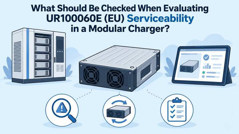
Engineers must determine how faults are identified, how the affected module is accessed, and what checks are necessary before the charger resumes operation. At UUGreenPower, our documented monitoring, communication, and hot-swap features provide a starting point for this assessment.
Check Fault Diagnosis and Monitoring Capabilities
A maintenance team should establish the likely fault location before removing hardware. The UR100060E (EU), an EV charging module, includes an LED indicator and HMI display that provide operating information such as voltage, current, address, operating mode, and fault status. CAN communication also supports system-level monitoring when correctly integrated with the charger controller.
These monitoring features can help technicians narrow the fault to the relevant functional area by comparing module status, controller logs, operating conditions, and electrical measurements. They should not be treated as proof that every fault can be isolated to the module without additional system-level diagnosis. For example, reduced output could result from a module fault, temperature-related derating, a controller issue, or a limitation elsewhere in the power path. Replacing a module without reviewing operating data may fail to resolve the original problem.
During evaluation, check whether the maintenance procedure identifies the information technicians should capture before intervention. Useful records include fault codes, operating conditions, module addresses, output measurements, and the event history available through the controller. Confirm the meaning of each alarm against the applicable technical documentation rather than relying on indicator color alone.
Evaluate Whether a Module Can Be Replaced Safely
The UR100060E (EU) supports hot swapping, a feature intended to facilitate module replacement in modular charging systems. However, this product capability should not be interpreted as permission to remove a module while energized under every installation condition. The approved system design and manufacturer instructions must define the circumstances in which replacement is permitted.
Inspect the cabinet layout to determine whether technicians can reach the module without removing unrelated assemblies. Check connector accessibility, handling space, mechanical retention, and the availability of a documented isolation procedure. The maintenance team should also know which electrical sources must be isolated and how the absence of hazardous voltage is verified.
A useful serviceability test is to document the complete replacement sequence using the intended cabinet configuration. Record each required step, tool, safety control, and dependency on another component. If replacement requires extensive dismantling or unclear procedures, the nominally modular design may still create unnecessary maintenance work.
Check Parallel Operation and Replacement Compatibility
The UR100060E (EU) supports parallel connection of up to 60 modules, according to its published product information. It also supports automatic address identification and manual address setting. These capabilities are relevant when evaluating replacement procedures because technicians must establish that the installed units are correctly identified and managed by the controller.
A replacement assessment should therefore cover more than physical fit. Confirm that the replacement model and hardware revision match the approved configuration, and verify firmware requirements, communication settings, and address assignment. Do not assume that visually identical units or different revisions are automatically interchangeable.
For example, after replacing one unit in a multi-module cabinet, the commissioning procedure should confirm that the controller recognizes the correct number of modules and reports their individual operating states accurately. Where parallel operation is used, verify that output sharing and fault handling behave as specified by the complete charger design.
A DC charger power module may support parallel expansion, but system compatibility still depends on the approved electrical and control configuration. Request written compatibility guidance whenever a proposed replacement differs from the original unit.
Account for Cooling and Environmental Maintenance
Serviceability also depends on whether the module can be maintained within the conditions of its installation. The UR100060E (EU) uses intelligent air cooling and has a specified operating temperature range of -40°C to 75°C, with derating from 55°C. These limits should inform maintenance planning, particularly for outdoor installations and high-utilization charging sites.
Inspect the cabinet's airflow path and determine whether technicians can check for obstructions, dust accumulation, or hot-air recirculation. The module's operating temperature range does not guarantee that a complete charger will maintain rated output under every ambient condition.
Maintenance plans should identify the inspections required by the actual enclosure design and installation environment. Record abnormal temperatures and recurring thermal alarms so that technicians can investigate the underlying cause rather than repeatedly replacing otherwise functional equipment.
Define the Evidence Required Before Returning to Service
A successful replacement is not complete until the charger has passed its prescribed return-to-service checks. UUGreenPower's monitoring and communication features can support verification, but the acceptance criteria must come from the approved charger design and applicable product documentation.
Use a maintenance record that captures the original fault, removed module identification, replacement unit details, configuration changes, and test results. Following replacement, verify communication, module recognition, reported operating values, alarm status, and normal operation using the authorized commissioning procedure.
A DC charger power module should be assessed within the complete system, including its controller, protection devices, cooling arrangement, and DC output path. Passing an individual module check does not by itself prove that the entire charger is ready for service.
At UUGreenPower, we recommend evaluating serviceability through demonstrated maintenance tasks rather than feature lists alone. Our UR100060E (EU) provides documented hot-swap support, CAN communication, address management, and operating-status visibility.
Together, these features establish a useful foundation, while cabinet accessibility, safe isolation, replacement compatibility, and post-maintenance verification determine how effectively the complete charging system can be restored. The strongest evaluation records both the product capabilities and the procedures required to use them reliably.
How Does UR100060E (EU) Affect Charger Cabinet Layout and Airflow?
2026-11-09 NextDiscovering the Best Charging Solution: UUGreenPower
2024-09-30

