
2026-11-09
UUGreenPower
0
In commercial EV charging solutions, a charger cabinet may accommodate the required power modules on paper but still face thermal or maintenance challenges after installation. Module dimensions, cooling arrangements, cable routing, and operating temperature all affect the enclosure’s ability to support continuous charging operation. For engineers integrating the UR100060E (EU), cabinet layout should therefore account for both the module’s physical dimensions and its cooling requirements.
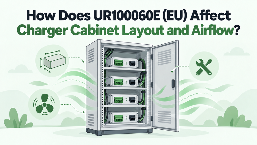
At UUGreenPower, we recommend treating mechanical integration and thermal management as connected design tasks. The UR100060E (EU) combines a compact module format with intelligent air cooling, so its placement and the cabinet's internal airflow deserve attention before the enclosure design is finalised. Official product information.
Giving the Module a Defined Place in the Enclosure
The UR100060E (EU) measures 300 × 125 × 437.5mm (W × H × D) and weighs no more than 25kg. These figures provide a starting point for estimating the space needed for each unit, but they do not define the complete installation envelope.
A cabinet drawing must also accommodate electrical connections, cable bends, mounting arrangements, and access for inspection or replacement. Engineers should confirm the manufacturer's installation clearances and mounting requirements before fixing the final module positions.
The number of modules also changes the layout. A cabinet designed around one unit has different wiring, access, and heat-management requirements from an enclosure populated with several units. We at UUGreenPower encourage system designers to establish the intended module count early, then assess whether the proposed arrangement leaves sufficient space for electrical integration and cooling.
Keeping the Cooling Route Clear
Intelligent air cooling makes airflow a central consideration when integrating the UR100060E (EU). The cabinet design should establish a continuous route for cooling air, with suitable inlet and exhaust arrangements based on the module's installation requirements.
Obstructions can compromise that route. Closely packed cable bundles, structural panels, neighbouring components, or poorly positioned ventilation openings may interfere with the intended airflow. Hot exhaust air returning to the intake can also raise the temperature of incoming air.
For a dc fast charging power module, cooling cannot be assessed solely by checking whether the fan or ventilation opening has physical clearance. Engineers should review the complete air path and confirm that the enclosure arrangement is consistent with the manufacturer's guidance.
Do not assume that a particular front-to-back or bottom-to-top airflow direction applies without checking the relevant installation documentation. The final layout should reflect the actual product configuration rather than a generic cabinet design.
Planning for Heat from the Complete Module Group
Thermal requirements become more demanding as the number of operating modules increases. Every module contributes conversion losses, and the cabinet must remove the resulting heat under the expected operating conditions.
The UR100060E (EU) has a specified peak efficiency of at least 97.5% and rated efficiency of at least 97%. At 62.5kW output and 97% efficiency, estimated input power is approximately 64.43kW, leaving about 1.93kW as conversion loss. This calculation illustrates the thermal load at that operating point rather than guaranteeing identical heat dissipation across all voltages, temperatures, and load levels. This calculation illustrates the relationship between output, efficiency, and losses; it is not a guaranteed heat-dissipation figure for every operating condition.
For a cabinet containing multiple units, engineers should assess aggregate losses at the intended loading level. The result helps inform the required cooling capacity and whether the selected enclosure arrangement can maintain suitable operating temperatures.
A higher module count should not automatically lead to tighter spacing. Mechanical density must be balanced against the cooling path, electrical clearances, and service access required by the complete assembly.
Using the Temperature Threshold to Guide Placement
The UR100060E (EU) has a stated operating temperature range of −40°C to 75°C, with derating beginning at 55°C. These specifications have different implications for cabinet design: the operating range defines the stated temperature envelope, while derating indicates that available output may need to be reduced above the specified threshold. See the official module overview.
Consider an outdoor charging installation exposed to strong sunlight. Heat absorbed by the enclosure, combined with heat generated by operating modules, may raise internal temperatures above the surrounding ambient temperature. The temperature at the module's air intake can therefore differ from a nearby weather reading.
Cabinet placement, ventilation, heat rejection, and expected charging load should be evaluated together. If the design could approach 55°C, obtain the applicable derating curve and use it to verify available output under the expected conditions. The threshold alone does not establish the precise output at every temperature.
Preserving Access Throughout the Service Life
A workable layout must support maintenance as well as initial assembly. Technicians may need to inspect connections, diagnose faults, or replace a module without unnecessarily disturbing adjacent equipment.
The UR100060E (EU) supports hot swapping, CAN communication, and automatic address identification or manual address setting. These features can inform maintenance and control-system planning, but they do not eliminate the need to follow approved replacement procedures and applicable electrical safety requirements.
Before releasing cabinet drawings, document module positions, cable routes, airflow passages, and maintenance access. Confirm that the proposed arrangement satisfies the installation instructions for the exact model and configuration.
Making the Enclosure Work with the Module
The UR100060E (EU) should be integrated as part of a complete mechanical, electrical, and thermal system. Its physical dimensions establish the initial space requirement; its air-cooling arrangement influences internal airflow; and its temperature-related derating behaviour affects output planning.
We at UUGreenPower advise system integrators to validate the intended module count, operating load, ambient conditions, cooling arrangement, and service envelope before finalising the cabinet. Our goal is to help designers evaluate the module against the requirements of their intended charging system, using confirmed product documentation rather than assumed clearances or airflow characteristics.
For a dc fast charging power module, successful integration depends on more than fitting the hardware into the enclosure. A layout that protects the cooling route, manages heat, and preserves service access provides a stronger foundation for reliable system operation. We at UUGreenPower recommend resolving these requirements during cabinet design, before mechanical constraints become expensive to change.
What Communication Should Be Checked Before Integrating the UR100060E (EU) with a Charger Controller?
2026-11-09 NextWhat Should Be Checked When Evaluating UR100060E (EU) Serviceability in a Modular Charger?
2026-11-10

