
2026-11-09
UUGreenPower
0
Integrating a power module with a charger controller requires more than confirming that both devices support the same communication interface. Engineers must establish how the devices exchange commands, identify operating states, report faults, and respond when communication is interrupted.
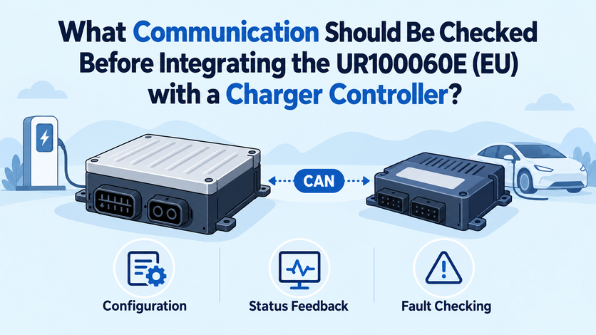
For the UR100060E (EU), the documented CAN interface provides the starting point, but successful integration depends on verifying the complete communication path against the controller's requirements.
EV Charging Module Integration: Commissioning and Compatibility Checks
The UR100060E (EU) supports CAN bus communication, automatic address identification, and manual address setting. Its LED and HMI display provide operating information, including voltage, current, address, operating mode, and fault status. These features provide useful starting points for commissioning and troubleshooting.
Before connecting an EV charging module to a charger controller, define the interface boundary. Identify the controller model, module model and revision, communication wiring, and the intended control architecture. Then obtain the applicable interface-control document or technical manual to confirm the electrical interface and communication settings.
CAN support alone does not establish compatibility between two devices. The controller and module must agree on message formats, addressing, transmission timing, and the meaning of exchanged information. If these details are undocumented, request confirmation rather than assuming that a generic CAN implementation will work.
Confirm CAN Settings Before Power-Up
The first communication check should cover the physical connection and configuration. Confirm the CAN wiring and connector pin assignments against the approved documentation, including signal polarity and any specified termination requirements. Incorrect wiring or bus configuration can prevent reliable message exchange even when both devices support CAN.
Next, verify the communication parameters that the controller and module are expected to share:
l - Bit rate: Confirm that both devices use the same configured CAN communication speed.
l - Message identifiers: Establish which CAN identifiers carry commands, measurements, status, and fault information.
l - Address assignment: Determine whether the integration uses automatic address identification or manual address setting, and confirm how each module is identified.
l - Timing and timeout: Check the expected message intervals, timeout thresholds, and behavior when valid messages stop arriving.
l - Startup configuration: Establish the required sequence for controller initialization, module detection, and communication readiness.
These are verification items, not a claim that every parameter is published in the product overview. The available UR100060E (EU) information confirms CAN communication and address-setting functions but does not establish every controller-specific setting. Request the relevant technical documentation before finalizing the configuration.
Check Commands, Feedback, and Fault Reporting
Communication is useful only when the receiving device interprets the information correctly. A controller may need to request an output voltage or current, monitor delivered values, and determine whether a module is ready to operate. The exact command set and message definitions must be confirmed from the module's interface documentation.
During integration, compare commanded values with measured output. The UR100060E (EU) specifies voltage-stabilized accuracy of ≤±0.5% and current-stabilized accuracy of ≤±1%. These are electrical regulation specifications, not communication-accuracy specifications. During integration, controller-reported values should therefore be compared separately with measured electrical output.
Fault reporting deserves an equally deliberate test. Confirm how the controller receives module fault states, distinguishes a warning from a shutdown condition, and determines whether operation can resume. Simulate only faults permitted by the approved test procedure. Record the reported status, controller response, recovery sequence, and any discrepancy between the displayed module status and controller logs.
A power module for EV charger integration should also be tested for communication loss. Disconnecting or interrupting the communication path under controlled test conditions can reveal whether the controller detects stale data and transitions to the defined safe state. The expected response must come from the approved system design, not from an assumed universal CAN behavior.
Keep Vehicle and Backend Protocols Separate
A DC charger contains several communication layers, and each has a different responsibility. CAN may connect the power module to the charger controller, while vehicle-facing charging protocols coordinate the charging session and backend protocols support communication between the charger and a charging management system.
The UMEV05 controller includes interfaces such as CAN, RS485/232, PLC, and 4G, while also supporting vehicle-facing charging protocols such as CCS1, CCS2, and CHAdeMO, together with OCPP 1.6/2.0 for backend communication. These functions operate at different communication layers and should not be treated as interchangeable. Support for the same physical interface also does not, by itself, prove UR100060E (EU) compatibility with a particular controller configuration.
This distinction matters during troubleshooting. If a vehicle cannot establish a charging session, the cause may lie in vehicle communication, controller logic, module control, or another part of the system. Engineers should inspect logs at the relevant interface instead of treating every communication issue as a CAN fault.
Prove the Interface Through Integration Tests
Before approving the assembled charger, run a structured test sequence using the intended controller, firmware, module configuration, and wiring. UUGreenPower recommends an evidence-based integration approach that separates component-level results from complete-charger acceptance.
The test record should cover module discovery, address assignment, startup, normal command and feedback exchange, output changes, fault reporting, communication interruption, recovery, and controlled shutdown. For parallel installations, verify that each module can be identified correctly and that the controller handles the intended configuration without confusing module status or measurements.
Record the software versions, communication settings, test conditions, observed results, and unresolved deviations. A successful bench test is valuable, but it does not establish that every cabinet configuration or controller revision will behave identically.
Reliable integration starts with documented interfaces, not assumptions. Before deploying the UR100060E (EU), confirm the CAN configuration, address-management method, message definitions, timeout behavior, and fault-response requirements.
Our specifications establish the module's communication capabilities; the final integration tests must establish that the selected controller and complete charger operate correctly together.
How Do Input and Temperature Conditions Affect System Selection for the UR100060E (EU)?
2026-11-09 NextHow Does UR100060E (EU) Affect Charger Cabinet Layout and Airflow?
2026-11-09

