
2026-08-06
UUGreenPower
0
Efficiency compares useful DC output with the real electrical power consumed at the input. Power factor compares real power with apparent power in an AC system, while harmonic distortion describes how far the current waveform departs from a sine wave. A highly efficient EV charging module can still require carefully designed power-factor correction. These measurements answer different questions and should not be combined into one performance claim.
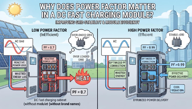
Power Factor and Grid-Side Performance
An AC supply must support both voltage and current. If current is poorly aligned with voltage or contains strong harmonics, the apparent power and RMS current can be higher than expected for the useful real power transferred. This affects transformers, cables, switchgear and the interaction between many chargers on the same facility supply. The complete charger's input behavior is the combined result of active conversion units, filters, auxiliary loads and cabinet controls.
Input-Current Shaping Through Power-Factor Correction
The input stage of an AC/DC charger commonly includes power-factor-correction circuitry. It controls current so the charger draws power in a more grid-compatible way while regulating an internal DC link. Performance changes with input voltage, phase balance, output load and control state. When units enter or leave service, the controller should maintain stable behavior. Start-up, light-load and derated conditions therefore deserve attention alongside full-rated operation.
Partial-Load Performance and Test Conditions
Why one headline value is incomplete. Power factor is usually highest near a defined rated condition and may change at partial load. THDi can also vary across the operating range. The EV charging module data should state the input voltage, load, temperature, measurement bandwidth and any external filters used. A value without conditions cannot be applied confidently to a cabinet operating with different numbers of active units or a different facility voltage.
Real-World Power-Factor Evaluation
A 240 kW charger assembled from several units may operate with only part of the pool enabled during a low-power session. Engineers should check how the remaining active units are loaded and whether this keeps them in a favorable input-performance region. They should also consider current balance among phases, transformer characteristics and other nonlinear loads at the site. The facility study should use complete-charger data whenever available.
How power factor relates to equipment sizing. Input current and apparent power influence conductor, protective-device and transformer selection. Harmonics may add heating or interact with other equipment, so applicable limits and assessment methods should be identified early. Correct sizing is a system engineering task: the module provides input characteristics, while the cabinet manufacturer and site designer coordinate filtering, distribution, protection and operating limits.
Buyer Data and Site-Level Verification
What buyers should request. For a fast charging power module, request power-factor and THDi data at representative load points, together with input range, test conditions and relevant standard references. Review start-up current, phase-loss behavior, input protection coordination and how the unit responds to voltage deviations. Then confirm complete-charger measurements with the proposed filters, auxiliaries and control sequence included.
Do not confuse displacement with total power factor. For a purely sinusoidal waveform, phase displacement explains much of the power-factor result. Power-electronic loads can also distort current, so total power factor reflects both displacement and distortion. This is why a specification should be read alongside harmonic data and test conditions. Engineers do not need to reduce the design to one formula, but they should avoid treating “current in phase” as complete proof of acceptable input behavior.
Complete-Charger Verification at the Point of Connection
The site assessment should finally confirm the combined charger behavior at the point of connection. Component data guides design, while complete equipment measurements show how filters, auxiliaries and controls interact in the installed configuration.
Recording partial-load results is especially useful for sites where chargers spend long periods below rated output.
Power factor matters because the grid sees the input behavior of the charger, not only its DC output. A well-integrated EV charging module supports controlled current draw alongside efficient conversion and stable parallel operation. UUGreenPower provides module specifications for integration; engineers should confirm the latest curves and complete-system compliance evidence for each project.
How Do AC/DC and DC/DC Charging Modules Differ in EV charging Systems?
2026-08-05 NextHow Do EV Charging Standards and DC Power Modules Work Together in a Fast Charger?
2026-08-06

