
2026-08-06
UUGreenPower
0
A DC fast charger must manage both information and energy. Charging standards define how the vehicle and charger connect, communicate, verify safety conditions, and control the session. The EV charger power module works at a different layer: it converts and regulates the electrical power that will ultimately reach the battery. Reliable charging requires these two functions to remain distinct while operating in close coordination.
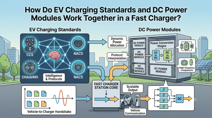
This distinction matters when discussing interfaces such as CCS, CHAdeMO, GB/T, or other regional charging approaches. A connector and communication standard does not perform high-power conversion, and a power unit does not become compatible with a charging standard merely because its voltage or rated power appears suitable. The complete charger must integrate the connector, communication controller, power stage, protection devices, switching equipment, cooling, and software as one verified design.
Three Functional Layers Inside a DC Fast Charger
A useful way to understand the charger is to divide it into three functional layers. The vehicle-interface layer includes the connector, cable, signaling hardware, and charging protocol. The control layer manages communication, session logic, safety states, power allocation, and fault response. The power-conversion layer changes the available input electricity into the regulated DC output required by the vehicle.
These layers exchange information, but they do not perform the same task. The vehicle communicates what it can accept. The charger controller determines what the complete equipment can safely deliver. The power stage follows the approved voltage and current commands. Keeping these responsibilities clear helps prevent the common assumption that one component alone provides charging-standard compatibility.
Charging Standards at the Vehicle Interface
At the vehicle-facing boundary, a charging standard governs the physical connection and the sequence used to establish a safe session. Depending on the interface, it may define connector contacts, communication methods, message timing, voltage and current negotiation, insulation checks, start conditions, controlled stopping, and abnormal-event handling.
Before high voltage is applied, the charger must recognize the connection and confirm that required conditions are satisfied. During charging, the vehicle continues to communicate allowable limits and status information. If the battery requests less current, reaches a stop condition, or reports an issue, the charger must interpret that information and adjust the energy-transfer process accordingly.
The Charger Controller as the Coordination Layer
The charger controller links the vehicle protocol to the power stage. It receives the vehicle’s requested voltage and current, compares them with the charger’s available capacity, and supervises contactors, insulation monitoring, emergency-stop logic, cable conditions, metering, and thermal limits. It may also allocate available power between multiple connectors or respond to a site-level load-management command.
After confirming that the requested operating point is permitted, the controller sends commands to the active power units. The EV charger power module then regulates its output and returns measurements, operating status, temperature information, and alarms. The controller uses that feedback to maintain the charging sequence or initiate a controlled reduction or shutdown when necessary.
Power Conversion at the Module Layer
The module layer is responsible for the physical conversion of energy. In an AC-fed charger, it commonly converts the facility’s AC input into controlled DC output. Depending on the charger architecture, separate or integrated stages may perform input-current shaping, electrical isolation, voltage transformation, rectification, and output regulation.
Several power units may operate in parallel to reach the cabinet’s required output. Their internal controls must support accurate current sharing, stable response, protection, and communication with the charger controller. The power stage must also remain within its defined input range, output curve, current capability, and thermal limits as the vehicle changes its request throughout the session.
Compatibility as a Complete-Charger Requirement
Support for a charging standard is a complete-charger property rather than a claim that can be assigned to one power component in isolation. Engineers must verify the connector and cable, vehicle-communication hardware, controller software, output-voltage range, current capability, contactors, pre-charge and discharge behavior, insulation monitoring, protection coordination, cooling, and applicable compliance requirements.
A properly selected EV charger power module provides the electrical range and controllability required by the charger design, but finished-equipment testing is still necessary to establish interoperability and safe operation. UUGreenPower supplies EV power-conversion products for charging-equipment manufacturers and system integrators. In the final charger, the standard organizes the vehicle-facing conversation, the controller translates that conversation into operating commands, and the power stage converts those commands into regulated DC energy.
Why Does Power Factor Matter in a DC Fast Charging Module?
2026-08-06 NextHow Do EV charging Modules Work with the Vehicle BMS During DC Fast Charging?
2026-08-06

