
2026-08-06
UUGreenPower
0
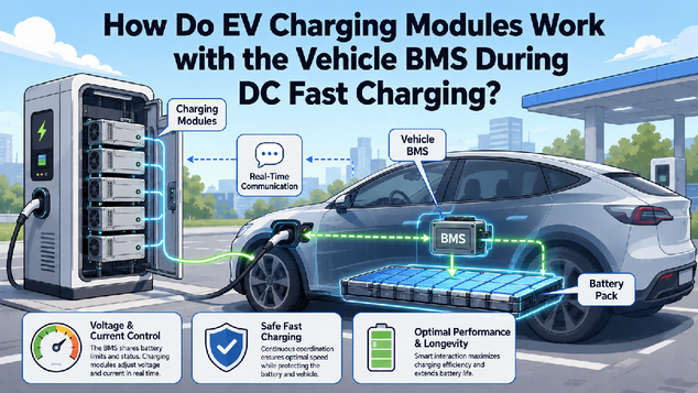
The vehicle battery-management system, or BMS, states what the battery can safely accept. The charger controller interprets the vehicle protocol and coordinates the station. The EV charging module follows voltage and current commands from that controller. The module and BMS therefore do not normally operate as a simple direct pair; the controller sits between them and owns the charging sequence.
Vehicle-Charger Communication at Session Start
After the connector is inserted, the charger and vehicle confirm connection, exchange information and perform safety checks. The charger evaluates insulation and prepares its output according to the applicable protocol and design. Only after the required checks and contactor sequence are complete does the controller command power delivery. Exact steps differ by charging standard, but the principle is consistent: the connector is not energized at full charging power merely because it is plugged in.
Shared Control Between the BMS, Controller, and Module
Battery voltage, temperature, state of charge and cell conditions change throughout a session. The BMS communicates allowable voltage and current so the charger can stay inside the battery's current limit. Near a high state of charge, requested current usually tapers. Cold or hot battery conditions can reduce the request earlier. These limits explain why a vehicle may draw less than the charger's nameplate power even when the charger has spare capacity.
The controller translates limits into power commands. The charger controller compares the vehicle request with connector current, cable temperature, cabinet capability, site power limits and active fault states. It then commands each active EV charging module to provide a share of the permitted output. The units measure actual voltage and current and report status. The controller uses this feedback to adjust commands, coordinate parallel current sharing and keep the station within all applicable boundaries.
Fault Handling, Safe Stops, and Integration Testing
A module may detect internal overtemperature, overcurrent or voltage faults. The cabinet may detect insulation, contactor or cable-temperature problems. The vehicle may reduce its request or stop because of a battery condition. Useful diagnostics should preserve which layer initiated the change. Treating every reduction as a module fault can lead to unnecessary replacement; ignoring a recurring module alarm can hide a genuine conversion or cooling problem.
Safe stopping is part of normal operation. When the vehicle requests a stop, the user cancels the session or a fault occurs, current should ramp down according to the system design before contactors open. Residual voltage must be discharged or confirmed safe as required. Communication timeouts, emergency-stop input and controller loss need defined responses. Engineers should validate these transitions, because steady-state output alone does not demonstrate safe session control.
Integrator Verification and Dynamic-Response Testing
What integrators should verify. A DC EV charger module should be checked for command ranges, measurement accuracy, ramp behavior, minimum output, communication timeouts, alarm mapping, emergency shutdown and post-fault state. The charger must then be tested with the intended protocol stack and representative vehicles or simulators. Tests should include changing requests, tapering, reconnects, communication interruption and a fault in one parallel unit.
Dynamic Charging Curves and Changing BMS Limits
The charging curve is a conversation, not a preset line. Online charging curves often show a smooth vehicle result under one set of conditions. In practice, the BMS can update limits repeatedly, and the charger responds within its own boundaries. Preconditioning, weather, recent driving and battery condition can change the curve. Engineers should therefore validate stable response to changing commands rather than tune the station for a single published profile. The system must remain safe and predictable across many valid vehicle requests.
Requested, Limited, and Delivered Power
For operators, the most useful comparison is requested power versus charger limit versus delivered power. That three-way view makes normal tapering visible and directs investigation toward the layer that is actually limiting the session.
The BMS protects the battery, the controller orchestrates the session, and the EV charging module delivers commanded power. Clear ownership between these layers is essential for reliable DC charging. UUGreenPower supplies charging modules for controller-based integration; finished-charger behavior must be validated against current protocol and vehicle requirements.
How Do EV Charging Standards and DC Power Modules Work Together in a Fast Charger?
2026-08-06 NextCan an EV charging Module Handle OCPP and Load Balancing on Its Own?
2026-08-07

