
2026-08-07
UUGreenPower
0
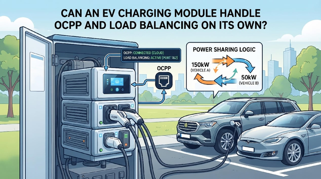
An EV charging module can report measurements and alarms, receive output commands and share current with parallel units. It does not usually operate the charging network's complete OCPP connection or decide a site's load-balancing policy. Those functions require knowledge of connectors, users, sessions, schedules, utility limits and backend commands, so they belong to charger controllers, site energy managers and network software.
OCPP and Load Balancing at the System Layer
OCPP supports communication between charging stations and a central system. Depending on the implementation, it can carry authorization, transaction, status, meter, configuration and smart-charging information. A power-conversion unit has neither the full station context nor the external network role. The charger controller or gateway maps hardware states into station-level messages and converts backend instructions into safe local actions.
Load balancing also needs broader information. Site load management compares the facility limit with building demand and the requests of all active charging ports. It may assign different power limits by priority, departure time or operational policy. Connector ratings, vehicle requests and cabinet conditions must be respected. The EV charging module contributes controllable output, but it cannot decide how much power another charger or non-charging building load should receive.
Module Response in Smart-Charging Operation
The controller can only implement a smooth power limit if conversion units respond predictably. Ramp rate, minimum stable output, enable timing, current-sharing accuracy and measurement latency all matter. If telemetry is delayed, the site controller may allocate power based on outdated information. If units respond too abruptly, the cabinet can overshoot or oscillate around a site limit. Hardware and software therefore remain closely connected even though their responsibilities differ.
Fault ownership must be mapped clearly. A backend communication loss should not be confused with a power-unit fault. Likewise, a unit overtemperature alarm should not be presented only as a network error. Integrators need an alarm map linking module conditions, charger-controller states and OCPP status or error reporting. Local safety functions must continue even when external communication is unavailable, while recovery behavior should follow the station's approved operating policy.
System Responsibilities and End-to-End Testing
UUinside describes PMU, ACU, DCU, DSU and CMS roles within a coordinated charging-system design. In this example, the PMU provides conversion, other hardware manages input and output paths, and supervisory control handles wider system decisions. The framework helps prevent software requirements from being assigned to the wrong component. Actual OCPP support still depends on the charger controller, gateway and backend implementation selected for the project.
Smart-Charging Integration Test Scope
What integrators should test. For an EV charger power module, verify command response, minimum and maximum output, current sharing, meter accuracy, alarm timing and behavior after controller communication loss. End-to-end tests should then cover changing site limits, multiple simultaneous sessions, backend interruption, local fallback, module derating and recovery. Cybersecurity, credential management and software updates should be addressed at the appropriate controller and operations layers.
End-to-End Command and Alarm Tracing
Trace one smart-charging command end to end. A useful test begins with a new power limit in the central system, follows it through OCPP to the charger controller, then compares the controller command with measured hardware output. The test should record timing, rounding, minimum limits and any reason the vehicle receives less. Reversing the trace for alarms confirms that module conditions reach the operator with the correct meaning. This method reveals gaps between individually functioning layers.
Interface-Control Documents and Responsibility Ownership
Ownership should be documented in an interface-control document. It can state which device hosts OCPP, which system calculates the site limit, how local fallback works and which hardware command represents that limit. This prevents duplicated logic or a gap in which every supplier assumes another component is responsible. The same document gives commissioning teams a clear set of end-to-end acceptance tests.
An EV charging module enables precise power adjustment but does not independently provide complete OCPP or site load management. UUGreenPower offers module and solution resources for integration; network compatibility and smart-charging behavior require coordinated system design and end-to-end validation.
How Do EV charging Modules Work with the Vehicle BMS During DC Fast Charging?
2026-08-06 NextHow Much Charging Power Does an EV Fleet Depot Need—and What Module Configuration Fits?
2026-08-07

