
2026-08-07
UUGreenPower
0
Fleet demand depends on vehicle count, route distance, energy use, arrival time, next departure and the energy each vehicle must receive. Only after those values are known should planners select charger output and the EV charging module arrangement. Multiplying every vehicle by a charger's maximum rating usually exaggerates simultaneous demand and says little about whether vehicles will actually be ready for service.
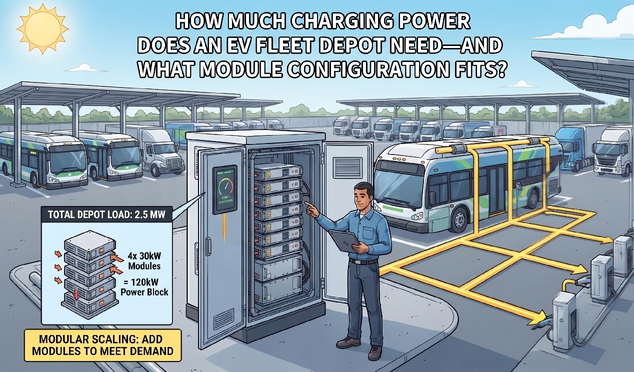
Fleet Operations and Energy-Demand Calculation
For each vehicle group, estimate energy used per route under realistic weather, payload and auxiliary-load conditions. Add an operational reserve, then identify how many hours are available for charging. Energy divided by time gives an average power requirement, but the schedule must also account for staggered arrivals, vehicles that complete multiple shifts and charging taper near high state of charge. Pilot data from representative vehicles is more useful than a single brochure consumption figure.
Site, Connector, and Module-Pool Sizing
A depot can have many connectors without providing maximum power to all of them simultaneously. Managed charging assigns available site power according to departure priorities and vehicle needs. Some vehicles may charge slowly for several hours, while another receives a temporary higher allocation before an early route. The electrical service, transformer, switchgear and energy-management limit define the site boundary; connector ratings define local boundaries.
Controlled-Peak Module-Pool Sizing
Select the module pool around the controlled peak. The EV charging module pool should support the depot's peak managed demand, voltage range and required connector allocation. A central power cabinet can share capacity across several dispensers, while separate chargers can provide stronger physical fault separation. The choice also affects cable routing, maintenance access and control complexity. Planners should model normal days, high-demand days and the effect of one unavailable charger or conversion unit.
Voltage and current need fleet-specific checks. Two vehicles with the same energy requirement may present different battery voltages and charging curves. At lower voltage, the charger needs more current to deliver the same power. Module and connector current limits can therefore constrain a low-voltage fleet even when total kW appears sufficient. Engineers should map the real fleet voltage window to the conversion unit's constant-power and current-limit curves.
Thermal Duty, Redundancy, and Disruption Validation
Depot charging can keep equipment active for long periods, especially when vehicles return together. Cabinet cooling and module derating must be evaluated for the actual ambient conditions and sustained load. Reserve capacity may allow planned maintenance or reduced-power operation after one unit is isolated. The required redundancy level should follow route criticality and the depot's ability to move a vehicle to another connector.
Final Sizing and Operational Simulation
What to verify before final sizing. When evaluating a DC fast charging power module, confirm voltage coverage, current at the fleet's lower battery voltages, parallel behavior, thermal derating, cooling, alarms and communication with the depot energy manager. Run a time-based simulation using vehicle arrival, required energy and departure deadlines. Then validate assumptions during a pilot, including cold-weather or high-temperature operation where relevant.
Disruption Scenarios and Recovery Capacity
Test the schedule against disruption. A useful model removes one connector or one block of power during the busiest return period. The planner can then see which vehicles miss their departure target and whether another connector can recover them. The same model should include a late arrival and a vehicle returning with more energy used than expected. These scenarios turn a power calculation into an operational plan and show where redundancy, driver procedures or schedule changes are genuinely needed.
After commissioning, the model should be updated with measured arrival times, energy use, charging curves and equipment availability. This feedback shows whether the original power allocation remains appropriate as routes, weather or fleet size change. Depot sizing is therefore not a one-time arithmetic exercise; it becomes an operating model that can guide controlled expansion and scheduling decisions.
Depot power is an operational scheduling problem supported by electrical design. The right EV charging module configuration follows route data, charging windows, vehicle voltage, site capacity and resilience targets. UUGreenPower provides module options for DC charging systems; project sizing should be completed with current fleet and site data.
Can an EV charging Module Handle OCPP and Load Balancing on Its Own?
2026-08-07 NextCan One Wide-Voltage Charging Module Support Both 400V and 800V EVs?
2026-08-07

